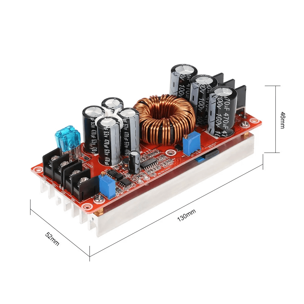
Description
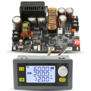
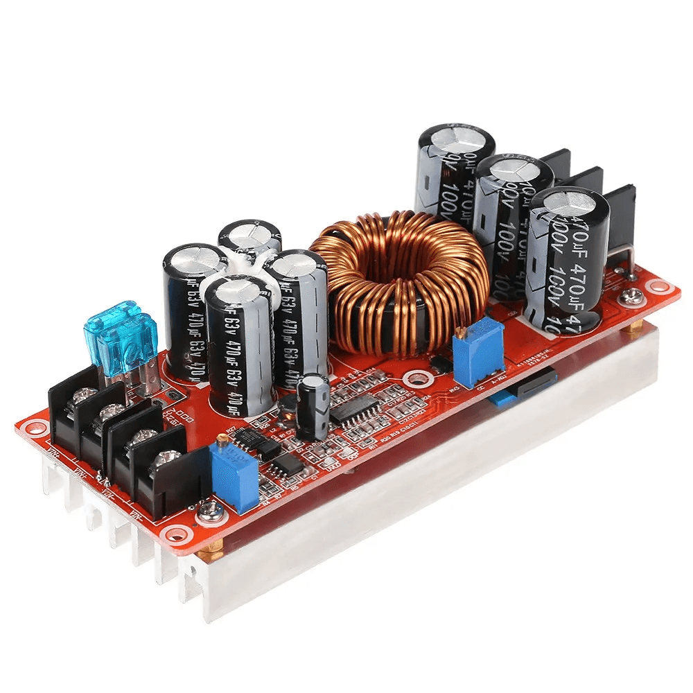
1200W 20A 97V Non-Isolated Boost Converter
This non-isolated boost converter raises a 10–60 V DC input to an adjustable 13–97 V DC output. It supports constant-current (CC) operation up to 20 A and constant-voltage (CV) operation. It can be used to power or charge batteries and other high-demand loads.
🔧 Technical specifications
- Input voltage: 10–60 V DC
- Output voltage: adjustable 13–97 V DC
- Output current: 0–20 A continuous (40 A peak when VIN ≥ 31 V)
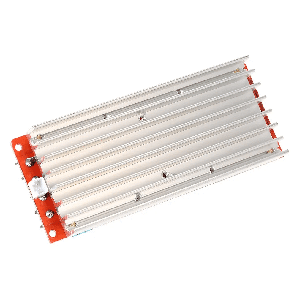
- Maximum power: 1200 W (with active cooling)
- Efficiency: 92–98%
- Switching frequency: approx. 110 kHz
- Protection: reverse polarity, input undervoltage, overload, short circuit, and over-temperature
- Operating temperature: −40 °C to +85 °C
- Dimensions: 130 × 51 × 80 mm (four Ø 3 mm mounting holes)
💡 Typical applications
- Boosting power from a 12 V battery for USB/CCTV equipment
- CC/CV charging of Li-ion, SLA, and other batteries
- Powering laptops or 48 V equipment
- DIY projects requiring a voltage higher than the battery voltage
- Solar-panel regulation for 48–60 V systems
🛠️ Operating guide
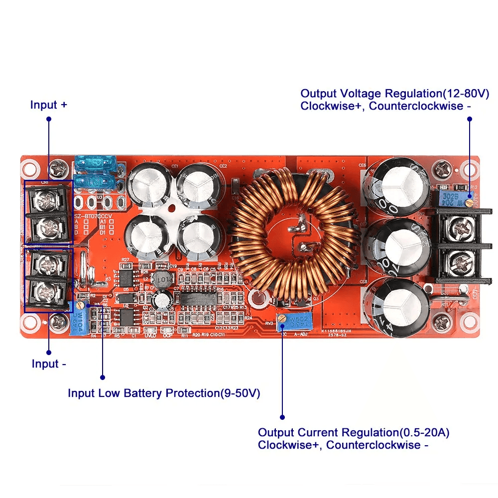
1. Wiring
- Connect VIN+ and VIN– to a 10–60 V source.
- Connect VOUT+ and VOUT– to the load or battery being charged.
2. Set the output voltage (CV)
- Make sure no load is connected.
- Turn the V-ADJ potentiometer clockwise to increase voltage or counterclockwise to decrease it.
- Check the voltage with a voltmeter before connecting the load.
3. Set the current (CC)
- Turn A-ADJ fully counterclockwise to set the current to its minimum.
- Connect the load (or a nearly discharged battery).
- Turn A-ADJ clockwise to the required current, checking it with an ammeter.
4. Set UVLO (input undervoltage lockout)
Power the module and turn the UVLO potentiometer until the undervoltage LED turns off, then turn it back by two turns to set the threshold.
5. Warnings
- Never reverse the VIN± or VOUT± polarity.
- For power above 500 W, provide an external fan.
- Do not operate continuously above 80% of maximum power.
- Avoid moisture and ensure good ventilation.
🛠️ Pinout / wiring
| Terminal | Function |
|---|---|
| VIN+ | Positive input (10–60 V DC) |
| VIN– | Negative input (ground) |
| VOUT+ | Positive output (13–97 V DC) |
| VOUT– | Negative output (ground) |
Connect the input first, adjust V and I, then connect the load to start powering it.
QS-4884CCCV boost module: adjustment trimmers
The 1200 W / 20 A boost module (QS-4884CCCV) has three multi-turn trimmers, each assigned to a separate function:
V-ADJ (Voltage Adjust)
- Sets the output voltage in CV mode.
- Turn clockwise to increase voltage and counterclockwise to decrease it.
- Adjust with no load connected and check the exact value using a voltmeter.
A-ADJ (Current Adjust)
- Sets the current limit in CC mode.
- Turn counterclockwise to reduce current to zero, then clockwise to the required current (measure with an ammeter in series).
- Adjust with the load—or a nearly discharged battery—connected to calibrate the actual current limit.
UVLO-ADJ (Under-Voltage Lockout Adjust)
- Sets the input-undervoltage threshold below which the module shuts down to protect the source.
- While adjusting, turn until the UVLO LED turns off (indicating cutoff), then turn back 1–2 turns to set the threshold.
- This helps prevent the input voltage (battery or supply) from falling below a critical level.
Note: The trimmers are multi-turn potentiometers for finer adjustment. Always verify settings with external instruments (voltmeter and ammeter) before connecting sensitive equipment.