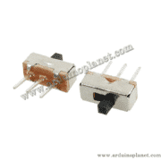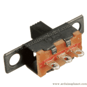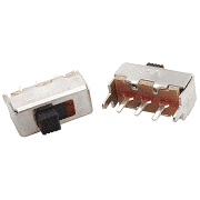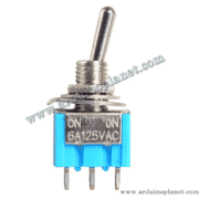
Description
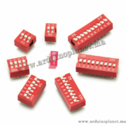
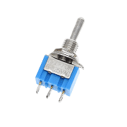
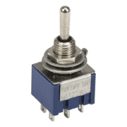
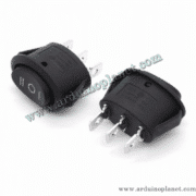
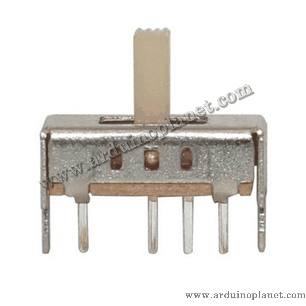
3-Position Slide Switch, 30 V DC, 0.5 A
This compact slide switch has three stable positions. It can select among modes, signals or circuit configurations. The slider stays in the selected position. It is a through-hole PCB component with manual slider operation.
Features
- Three stable positions
- Compact format
- For low-voltage circuits
- Announced service life: 10,000 cycles
Technical specifications stated in the source listing
- Maximum rated voltage: 30 V DC
- Maximum rated current: 0.5 A
- Contact resistance: ≤ 0.03 Ω
- Insulation resistance: ≥ 500 MΩ
- Insulation test voltage: 500 V AC for 1 minute
- Approximate service life: 10,000 cycles
- Mounting: through-hole PCB
The 500 V AC value is a short-duration insulation test, not the switch’s normal operating voltage. The source-listed maximum operating rating is 30 V DC, 0.5 A.
How it works
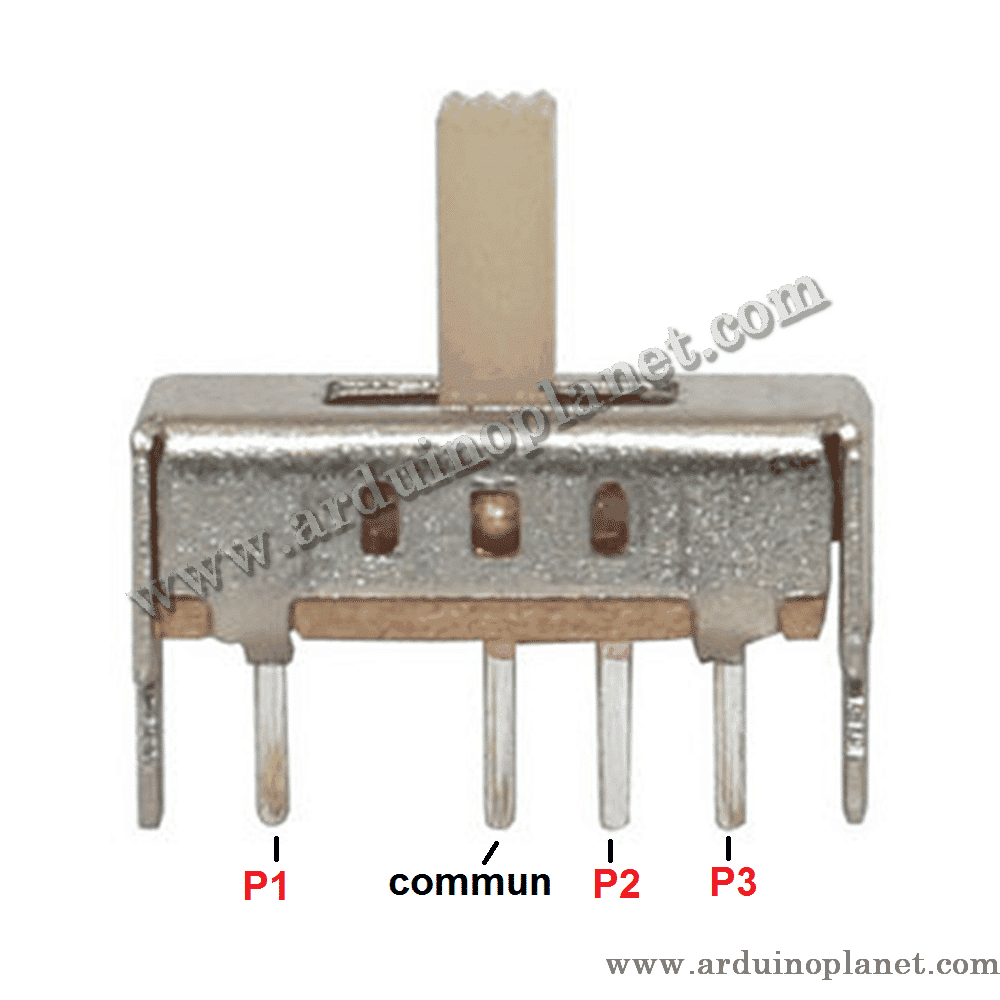
The slider moves an internal metal contact. Depending on its position, it connects the common terminal to another terminal or establishes a different contact combination. The exact connection diagram depends on the pinout of this version.
Identify the pinout
- Set a multimeter to continuity mode before soldering the switch.
- Place the slider in the first position.
- Test combinations of pins and note which ones are electrically connected.
- Move the slider to the middle position and repeat the measurement.
- Repeat for the third position.
- Identify the common terminal or terminals.
- Draw a connection table before wiring the circuit.
This procedure helps avoid wiring errors when the pinout is not printed on the component.
Example: selecting among three signals
- Identify the common terminal with a multimeter.
- Connect it to the circuit input you want to control.
- Connect the selected contacts to the different signals or functions.
- Keep the voltage below 30 V DC and current at or below 0.5 A.
- Test each position before final soldering.
- Insulate exposed connections properly.
For loads above 0.5 A, use the switch only as a control signal for a suitably rated relay, transistor or MOSFET.
Example: selecting a level
Position 1 → Resistor R1 → Low level
Position 2 → Resistor R2 → Medium level
Position 3 → Resistor R3 → High level
With a suitable electronic circuit, this arrangement can select a speed, brightness, audio gain or reference value.
Safety precautions
- Stay within the source-listed limit of 30 V DC and 0.5 A.
- Do not connect this switch directly to 220–230 V mains.
- Disconnect power before changing wiring.
- Check the pinout with a multimeter before soldering.
- Do not directly switch a motor or a significant inductive load.
- Use suitable protection for relays, coils and small motors.
- Avoid heating the pins for too long while soldering.
- Do not force the slider beyond its three positions.
Typical applications
- Selecting one of three modes
- Audio circuits and input selection
- Lighting-level selection
- Speed control with a suitable circuit
- Arduino and robotics interfaces
- Battery-powered devices
- Electronic toys and controllers
- Prototypes and DIY circuits
- Small control panels
- Electronics training exercises
Keywords: slide switch, 3-position switch.