Description
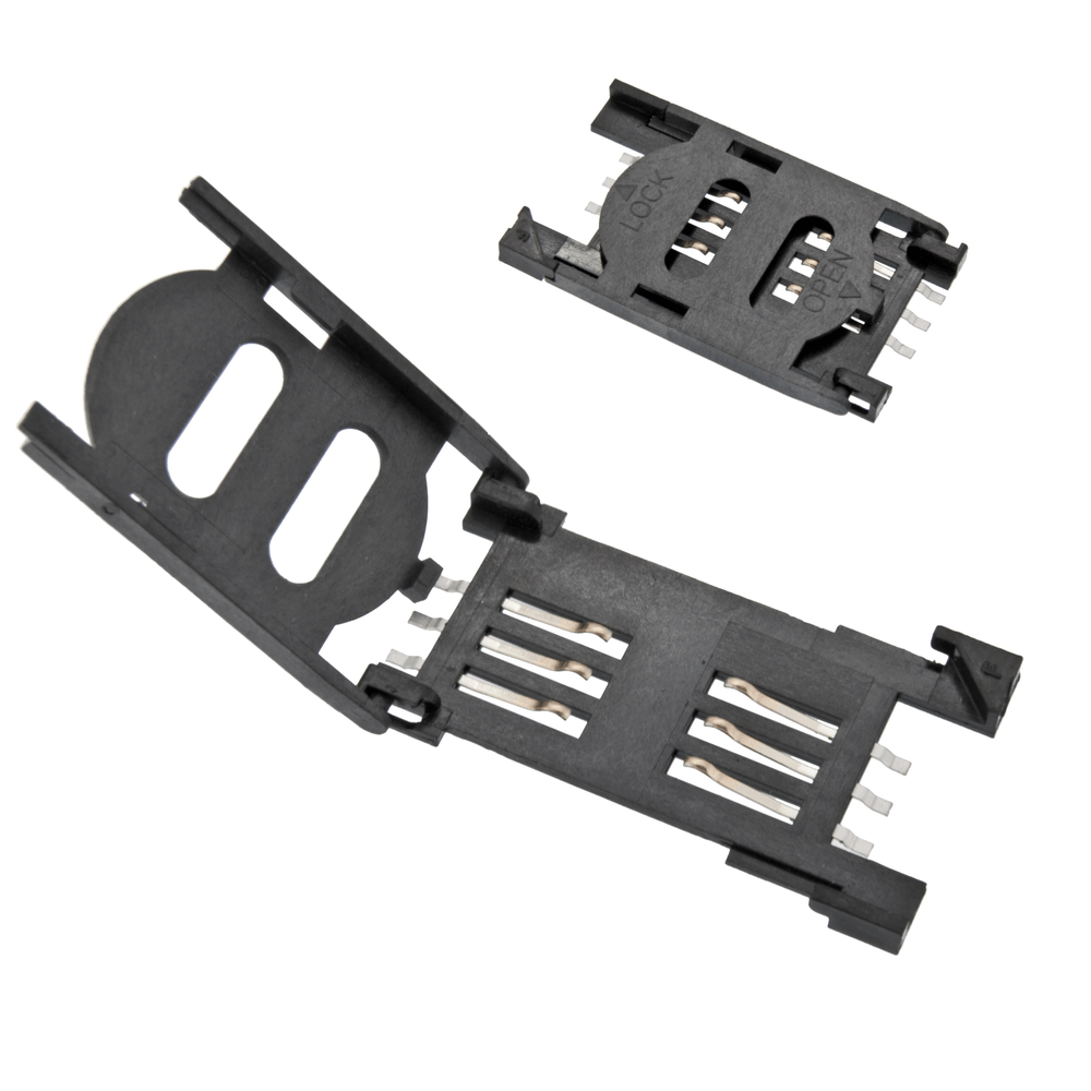
6-Pin SIM Card PCB Connector
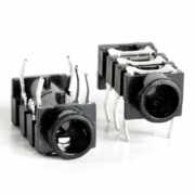
This six-pin SIM card connector provides a physical and electrical connection between a SIM card and a compatible GSM/LTE module or communication circuit. It is designed for PCB mounting.
Key features
- Connector type: mechanical SIM card holder/connector
- Contacts: six
- Mounting: PCB
- Electrical interface: intended for SIM ISO/IEC 7816 signals
- SIM supply: provided by the GSM/LTE module
- Integrated modem: no
- Integrated level conversion: no
- ESD protection: not specified
- Card-detect switch: not specified
- SIM card included: no
Check the physical card size and connector shape against the drawing. Six contacts alone do not identify whether the holder accepts Mini-SIM, Micro-SIM or Nano-SIM.
Typical six SIM contacts
A standard SIM interface commonly uses the following contacts:
| SIM contact | Signal | Function |
|---|---|---|
| C1 | VCC | SIM card supply |
| C2 | RST | Reset |
| C3 | CLK | Clock |
| C5 | GND | Ground |
| C6 | VPP | Legacy programming voltage, often unused |
| C7 | I/O | Bidirectional serial communication |
C4 and C8 on a standard SIM are generally unused. Physical connector pin layout can vary; identify the contacts from the PCB footprint or with a multimeter before designing the circuit.
How it works
The connector does not read SIM information by itself. It provides the mechanical and electrical contact between the card and a compatible circuit. The GSM/LTE module supplies the appropriate voltage, generates the clock, resets the card and communicates over the I/O line. The module then uses the SIM information to access the mobile network.
An Arduino alone cannot use a SIM card directly without a modem or compatible SIM interface.
Functional diagram
Carte SIM
   │
Connecteur 6 broches
   │
VCC • RST • CLK • I/O • GND
   │
Module GSM / LTE
   │
UART, USB ou autre interface
   │
Microcontrôleur
Integration guide
- Check that the SIM card format matches the holder.
- Consult the GSM/LTE module datasheet.
- Identify the holder contacts with a multimeter.
- Connect VCC to the modem SIM_VCC output.
- Connect RST to SIM_RST.
- Connect CLK to SIM_CLK.
- Connect I/O to SIM_DATA or SIM_IO.
- Connect GND to the module ground.
- Leave VPP unconnected unless the modem documentation specifies otherwise.
- Add suitable ESD protection near the connector.
- Insert or remove the card only when the circuit is powered off.
- Check card orientation before powering on.
Keep SIM traces short and away from antennas, switching converters, motors and other sources of interference.
Voltage and logic levels
Modern SIM cards commonly use a voltage selected by the modem, often 1.8V or 3V.
- Do not connect VCC directly to an Arduino 5V pin.
- Do not apply 5V logic levels directly to RST, CLK or I/O.
- Use the modem dedicated SIM outputs.
- Check the voltage requirements of both the card and module.
An incorrect voltage can immediately damage the SIM card.
Design notes
- Place the connector near the cellular module.
- Use a clean ground plane.
- Add low-capacitance ESD protection.
- Avoid long traces on CLK and I/O.
- Do not route SIM traces beneath an RF antenna.
- Check solder quality on the mechanical mounting tabs.
- Allow access for card replacement.
- Never force the card if its orientation is wrong.
Applications
- Compatible GSM, GPRS, 3G, 4G or LTE modules
- Connected GPS trackers
- Alarms with mobile notifications
- Home automation systems
- Telemetry stations
- Communication terminals and equipment
- Industrial automation
- IoT projects
- SIM reader repair
- Mobile device design