Description
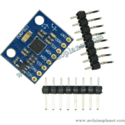
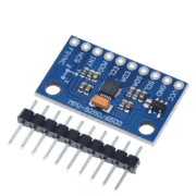
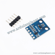
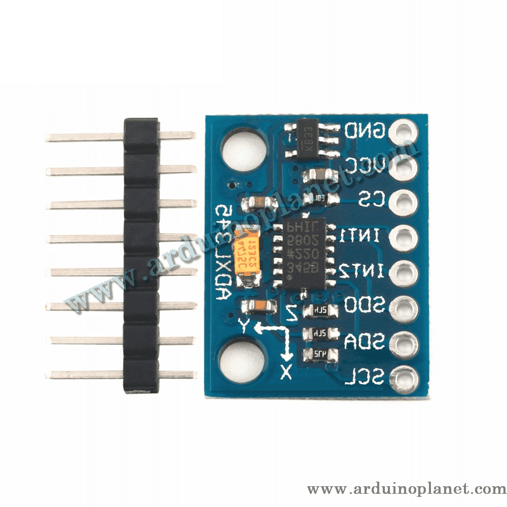
ADXL345 3-Axis Digital Accelerometer and Tilt Sensor Module
This board uses an ADXL345 digital accelerometer to measure acceleration on three axes. It can sense motion, vibration, impact and the direction of gravity for tilt-related calculations. It does not directly measure angular rotation like a gyroscope; tilt estimates are best when the device is stationary or moving slowly.
🔧 Sensor specifications
- Axes: 3-axis digital acceleration measurement
- Selectable full-scale ranges: ±2 g, ±4 g, ±8 g and ±16 g
- Resolution: up to 13-bit measurement in full-resolution mode; output registers are formatted as 16-bit data
- Digital interfaces: SPI (3- or 4-wire) or I²C, depending on board wiring/configuration
- Chip supply voltage: 2.0–3.6 V; the listing states 3–5 V for the breakout board. Carrier boards vary, so check whether this exact board includes a regulator and level shifting. Do not apply 5 V directly to the ADXL345 chip.
- I/O voltage range at the chip: 1.7 V up to its supply voltage; do not assume the board’s SPI/I²C pins are 5 V tolerant without confirming the board design
- Current stated in the listing: 30 µA. The ADXL345 datasheet gives approximately 30 µA at output rates below 10 Hz and approximately 140 µA at rates of 100 Hz or higher; board overhead adds to this.
- Operating temperature stated: −40 °C to +85 °C
📐 Tilt and motion measurements
The accelerometer reports acceleration, including gravity when stationary. Software can estimate static tilt from the gravity vector, but dynamic movement and vibration affect the readings. For smoother estimates, filter the data and calibrate offsets. The selectable g range is a measurement limit: choose a wider range for stronger impacts or a narrower range for greater sensitivity to small accelerations.
The device also includes functions such as activity/inactivity, tap and free-fall detection, subject to configuration in firmware. An accelerometer alone cannot provide drift-free rotation or full 3D heading; those applications may need a gyroscope and, for heading, a magnetometer.
⚙️ Wiring and setup
Connect the board’s documented supply and ground, then connect either SDA/SCL for I²C or the appropriate SPI signals. Check the board’s interface selection, address/pin configuration, supply input and logic levels before wiring it to a 5 V Arduino or other host. Use a level shifter if the breakout does not provide one.
Mount the sensor securely and note its axis orientation. Select the output rate and measurement range in software, and allow for sensor noise, offsets, temperature effects and board alignment when interpreting readings.
💡 Typical uses
- Motion, tilt, vibration and impact sensing
- Free-fall and tap detection prototypes
- Microcontroller and robotics projects
- Educational experiments with acceleration and gravity
Measurement accuracy depends on calibration, mounting, vibration, temperature and software. This is a development module, not a certified safety or navigation device.