Description
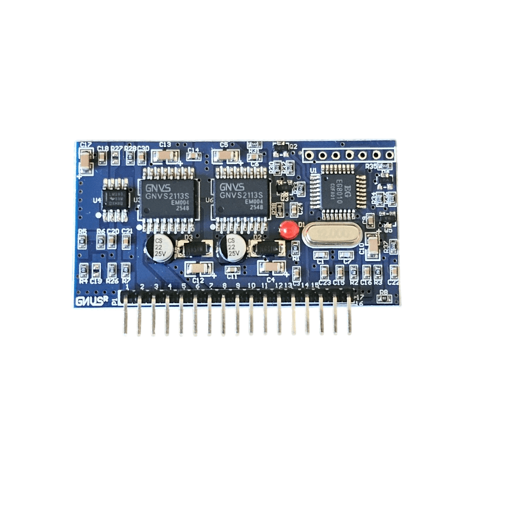
EGS002 Pure Sine Wave Inverter Controller Board
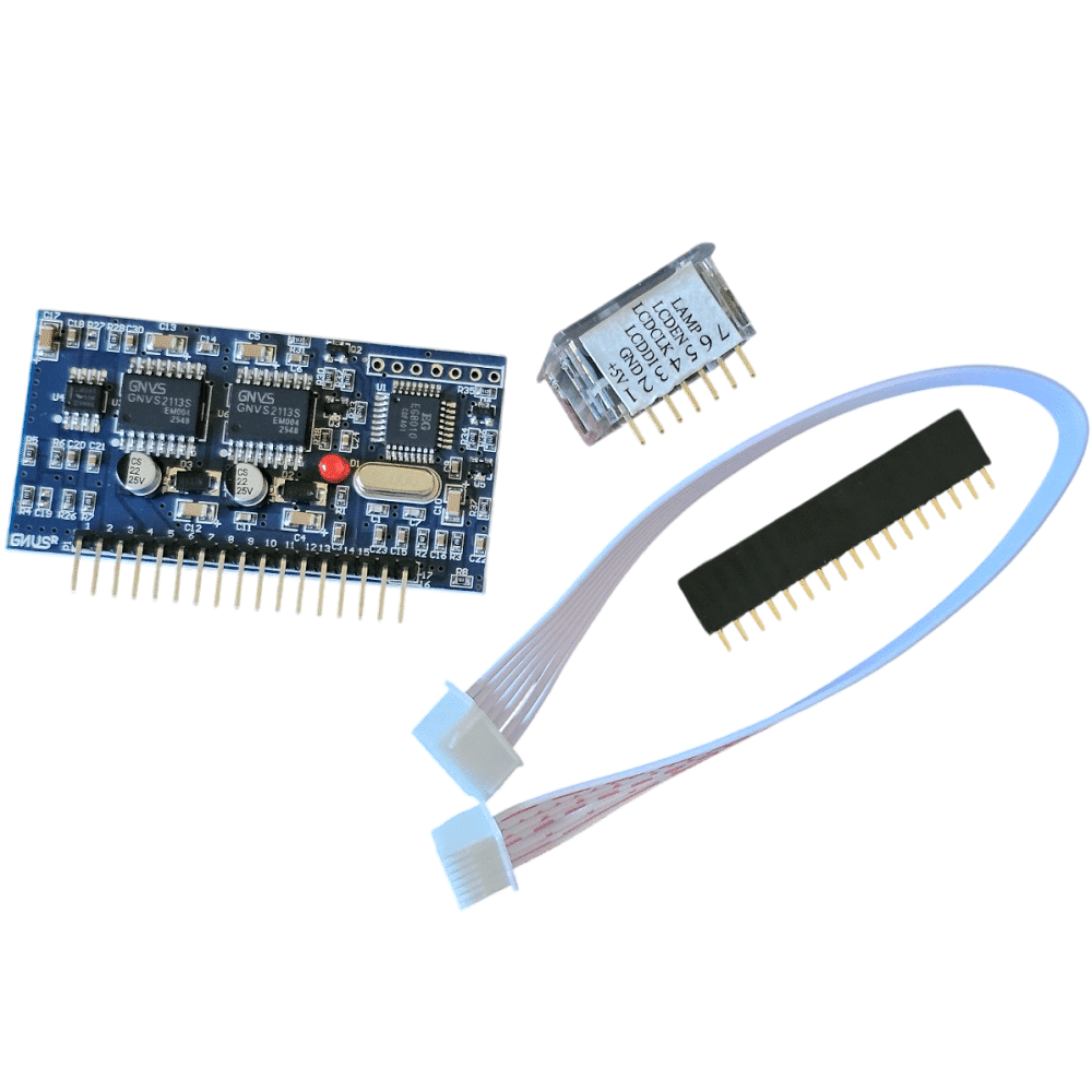
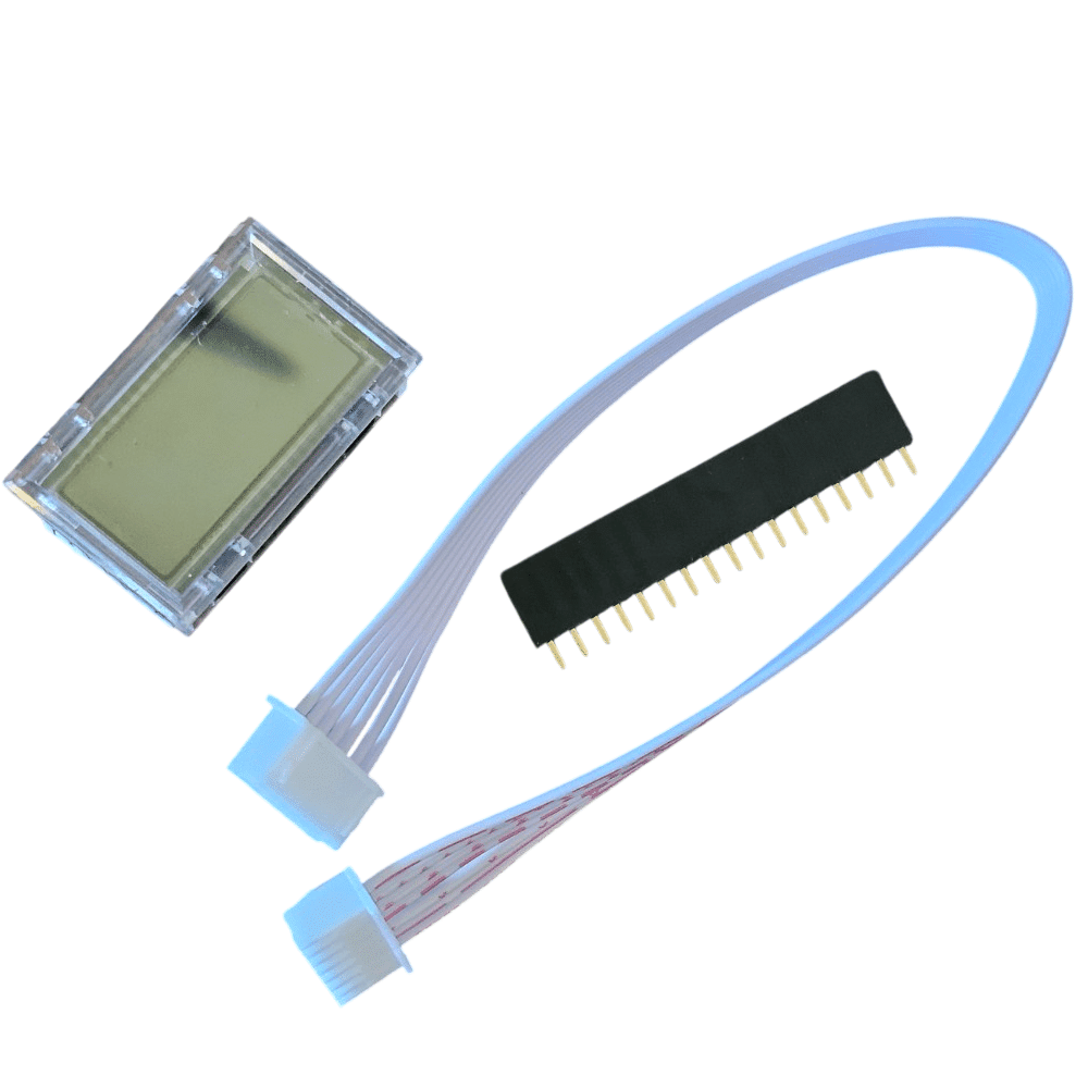
The EGS002 is a single-phase inverter controller board based on the EG8010 and IR2113. The listing describes a 5V supply, selectable sine-wave frequency, unipolar or bipolar modulation, adjustable dead time, soft start, voltage/current/temperature feedback, protection functions, serial configuration and an optional 128 × 32 serial LCD module. Select the EGS002 board or the display option.
Listed features
- Supply: 5V
- Output frequency selections: fixed 50Hz, fixed 60Hz, adjustable 0–100Hz or adjustable 0–400Hz
- Unipolar and bipolar modulation
- Dead-time selections: 300ns, 500ns, 1.0µs or 1.5µs
- External 12MHz crystal; PWM carrier frequency: 23.4kHz
- Real-time voltage, current and temperature feedback; listed overvoltage, undervoltage, overcurrent and overtemperature protection
- Pin-selected soft-start response stated as 1s; the feature list also describes a 3s jumper setting
- Serial setting of output voltage, frequency and other parameters
- Optional serial 128 × 32 LCD for inverter readings
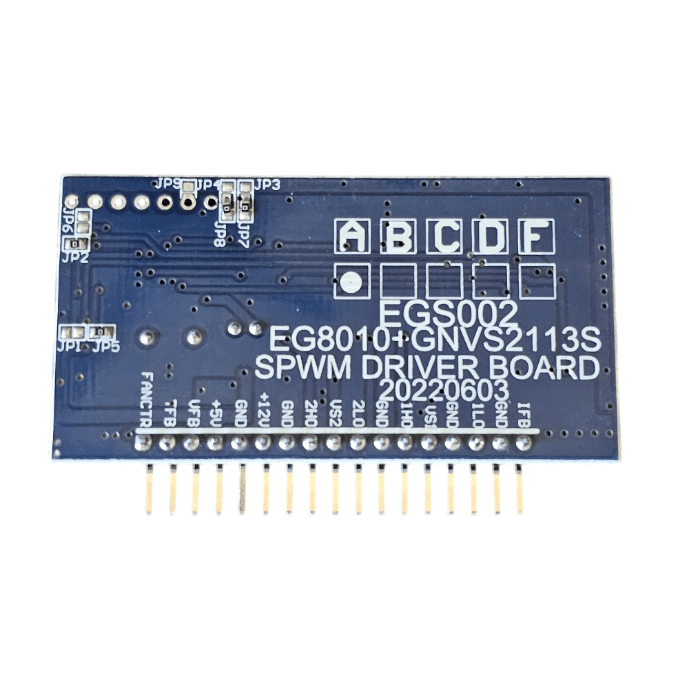
EGS002 pinout
| Pin | Signal | I/O | Description |
|---|---|---|---|
| 1 | IFB | I | Input above 0.5V triggers overcurrent protection |
| 2 | GND | GND | Ground |
| 3 | ILO | O | Right-bridge low-side MOSFET driver output |
| 4 | GND | GND | Ground |
| 5 | VS1 | O | Right-bridge high-side return |
| 6 | 1HO | O | Right-bridge high-side MOSFET driver output |
| 7 | GND | GND | Ground |
| 8 | 2LO | O | Left-bridge low-side MOSFET driver output |
| 9 | VS2 | O | Left-bridge high-side return |
| 10 | 2HO | O | Left-bridge high-side MOSFET driver output |
| 11 | GND | GND | Ground |
| 12 | +12V | +12V | 12V DC input; stated range 10–15V |
| 13 | GND | GND | Ground |
| 14 | +5V | +5V | 5V DC supply |
| 15 | VFB | I | AC output-voltage feedback for regulation |
| 16 | TFB | I | Temperature monitoring; listing states overtemperature protection at 4.3V |
| 17 | FANCTR | O | Fan control: high above 45°C and low below 40°C, as listed |
LCD connection
| Pin | Signal | I/O | Description |
|---|---|---|---|
| 1 | +5V | P | LCD supply |
| 2 | GND | GND | Ground |
| 3 | LCDDI | I/O | Serial LCD data |
| 4 | LCDCLK | O | Serial clock |
| 5 | LCDEN | O | LCD chip select |
| 6 | LED+ | P | Backlight supply |
| 7 | LED- | GND | Backlight ground |
Jumper settings listed
| Function | Jumper | Setting stated in source |
|---|---|---|
| Frequency (FS0) | JP1 / JP5 | JP1 shorted: 60Hz; JP5 shorted: 50Hz |
| Soft start (SST) | JP2 / JP6 | JP2 shorted: 3s soft start; JP6 shorted: soft start disabled |
| Dead time (DT0) | JP3, JP7, JP8 | JP7 + JP8: 300ns; JP3 + JP8: 500ns |
| Dead time (DT1) | JP4, JP7, JP3 | JP4 + JP7: 1.0µs; JP3 + JP4: 1.5µs |
| LCD backlight | JP9 | Shorted: on; open: off |
Default settings stated in the listing: 50Hz (JP5 shorted), soft start enabled (JP2 shorted), and 300ns dead time (JP7 and JP8 shorted). The source gives differing soft-start timing details (1s and 3s); check the board revision and its documentation before wiring or configuring it.
Applications listed include single-phase sine-wave inverters, photovoltaic and wind inverters, UPS systems, digital generator systems, single-phase motor speed controllers, dimmers and sine-wave generators. This is a controller board, not a complete inverter. Use appropriate power-stage design, isolation, protection and qualified electrical practices.