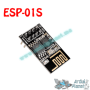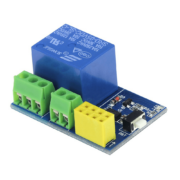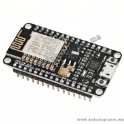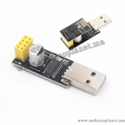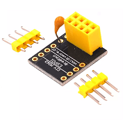
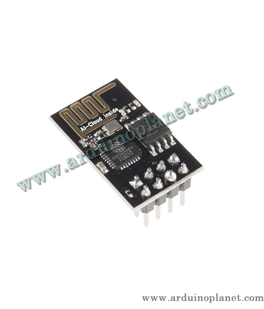
Description
ESP-01 Wi-Fi Module with ESP8266
The ESP-01 is a compact Wi-Fi module built around the ESP8266 system-on-chip. It can be programmed to run a small application on its own or used as a Wi-Fi/network interface for a separate microcontroller over UART. Which approach is suitable depends on the firmware and the limited pins exposed by the ESP-01 board.
🔧 Listed and chip-reference specifications
- Wi-Fi: IEEE 802.11 b/g/n on the 2.4 GHz band
- Built-in TCP/IP networking support
- UART serial interface; the listing states 115,200 bps, which may be configurable by firmware
- Supply and GPIO logic: 3.3 V; ESP8266 operating range is 2.5–3.6 V. Do not apply 5 V to the module or its GPIO pins.
- Average/current figures in the listing: approximately 70 mA nominal and up to approximately 300 mA; Wi-Fi transmit bursts can draw much more current than idle operation
- Recommended supply design: stable 3.3 V source with adequate headroom; Espressif recommends at least 500 mA output capacity for ESP8266 modules
- RF transmit-power figure stated by the listing: up to +19.5 dBm in 802.11b mode
- Flash capacity stated by the listing: 512 Kb; confirm the memory size of the exact board revision
- Wi-Fi security listed: WPA/WPA2, subject to the firmware, configuration and network security supported
- Board dimensions stated by the listing: 24.75 × 14.5 mm
📌 ESP-01 pin and GPIO note
The ESP8266 chip provides programmable GPIO, but the ESP-01 is a small board and exposes only a limited set of pins. Do not assume that all GPIO available on other ESP8266 boards are accessible here. UART and boot-mode pins also have specific functions; check a pinout for the exact ESP-01 revision before wiring.
⚙️ Power and programming
Power the module from a clean, stable 3.3 V supply sized for Wi-Fi current bursts. A weak regulator or long, thin wires can cause resets or failed connections. The 3.3 V output on some Arduino boards may not supply enough current. Use a shared ground with the host controller.
Use a 3.3 V UART adapter or a suitable level shifter when programming or communicating with the module. A 5 V UART TX signal can damage the ESP8266 RX/GPIO. Flashing firmware may also require the correct boot-mode pin states and reset sequence; follow the procedure for the exact board.
🌐 Typical uses
- Connecting a microcontroller project to a 2.4 GHz Wi-Fi network
- Simple web, sensor and IoT prototypes
- Standalone ESP8266 experiments with supported firmware
- Network communication over TCP/IP for compatible applications
Wi-Fi range, throughput and security depend on antenna layout, power quality, firmware, router and radio environment. This development board is not a certified security or safety device.