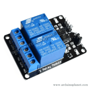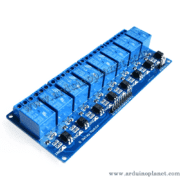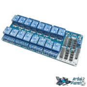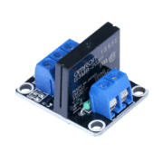
Description
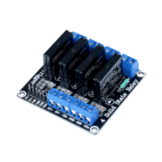
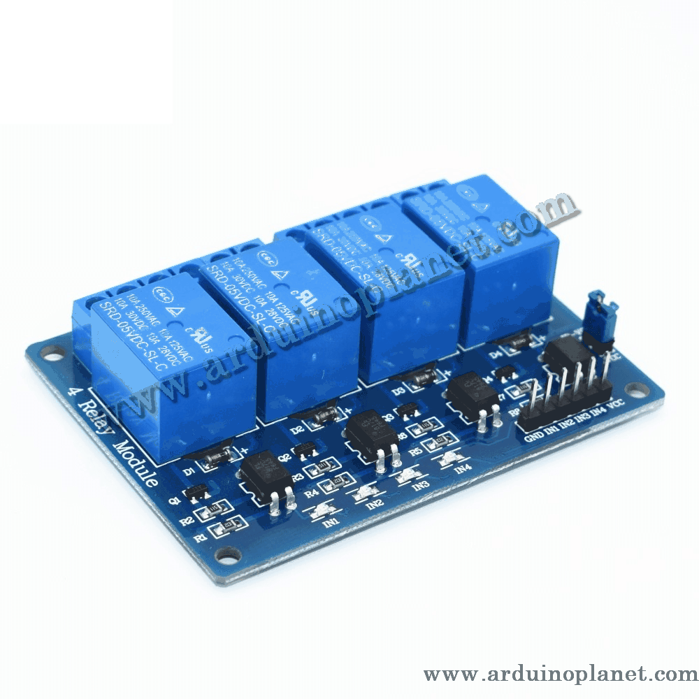
4-Channel 5V Relay Module
The 5V four-channel relay module is a switching device for controlling AC and DC loads. It is compatible with microcontrollers such as Arduino and Raspberry Pi, allowing electrical devices to be controlled remotely.
Detailed Specifications
- Relay type: Electromechanical relay
- Number of channels: 4
- Control voltage: 5V DC
- Rated current: 10A
- Contact configuration: SPDT (Single Pole Double Throw)
- Load rating: AC250V 10A, DC30V 10A
- LED indicators: Indicate relay status
- Dimensions: 92 x 46 x 20 mm
- Trigger: Active LOW
- Isolation: Optocoupler isolation
How It Works
An electromagnetic coil activated by a 5V control voltage opens or closes the relay contacts. This lets a low-voltage control signal switch higher-power electrical loads while providing effective isolation and reliable switching.
Applications
- Industrial automation: Switching motors, heaters, and other industrial equipment.
- Security systems: Activating sirens or signaling devices in alarm systems.
- Home automation: Controlling lighting and electrical appliances in smart homes.
- Electronics projects: Prototyping and development with Arduino and other microcontrollers.
How to Use It with an Arduino Uno
Required components:
- 1 x 5V 4-channel relay module
- 1 x Arduino Uno
- Connecting wires
- Breadboard
Wiring instructions:
- Power the module: Connect VCC to the Arduino 5V pin and GND to Arduino GND.
- Control inputs: Connect IN1 through IN4 to Arduino digital outputs (for example, pins 7, 8, 9, and 10).
- Load connections: Connect the relay output terminals (NO and COM) to the load. NO is normally open and closes when the relay is activated.
Arduino Uno code example:
const int relaisPins[4] = {7, 8, 9, 10}; // Pins de commande des relais


void setup() {
  for(int i = 0; i < 4; i++) {
    pinMode(relaisPins[i], OUTPUT); // Définit chaque pin de commande comme une sortie
  }
}


void loop() {
  for(int i = 0; i < 4; i++) {
    digitalWrite(relaisPins[i], LOW); // Active chaque relais
  }
  delay(5000); // Attend 5 secondes


  for(int i = 0; i < 4; i++) {
    digitalWrite(relaisPins[i], HIGH); // Désactive chaque relais
  }
  delay(5000); // Attend 5 secondes
}
Code Explanation
- Control pin declaration: Arduino Uno pins 7, 8, 9, and 10 are configured as outputs for the relays.
- Relay setup: In
setup(), the control pins are initialized as outputs. - Main loop:
- Each relay is activated with a LOW signal on its control pin, closing the connected circuit.
- The program waits 5 seconds.
- The relays are deactivated with a HIGH signal, opening the circuits.
- The program waits another 5 seconds before repeating.
Pinout
- VCC: 5V power supply
- GND: Ground (GND)
- IN1 to IN4: Control inputs for the relays, connected to Arduino digital outputs
- NO1 to NO4: Normally open terminals, connected to each load
- COM1 to COM4: Common terminals, connected to the load’s power supply
Keywords: solid-state relay, 4-channel module, industrial automation, automatic lighting, home automation, relay, channel.