Description
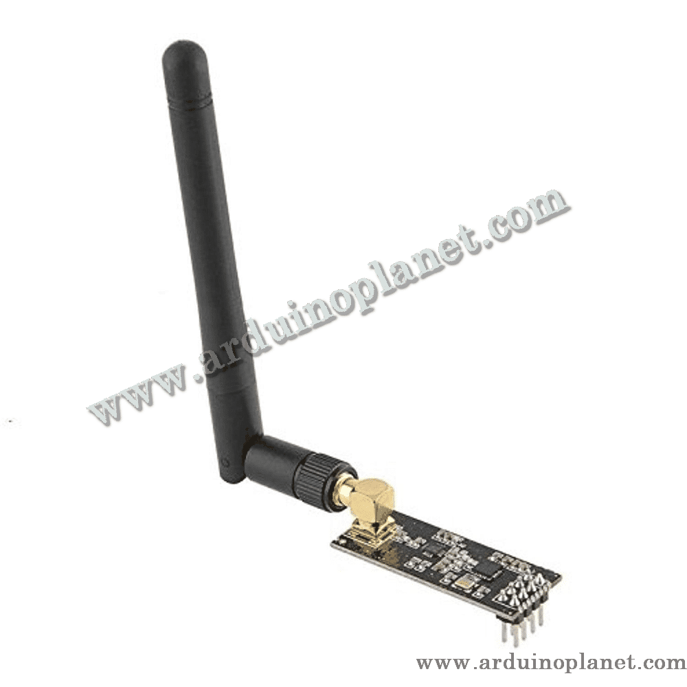
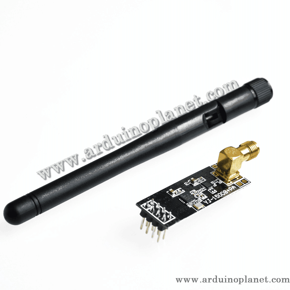
nRF24L01 2.4 GHz Wireless Transceiver Module with Antenna
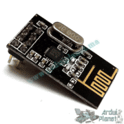
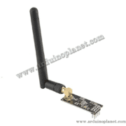
This radio module is based on an nRF24L01-family transceiver and adds an external antenna for a 2.4 GHz wireless link. It connects to a microcontroller through SPI and is intended for communication between compatible radio modules running suitable firmware. It does not connect directly to Wi-Fi or Bluetooth devices.
🔧 Chip and listing specifications
- Radio band: 2.4 GHz ISM
- Radio supply voltage: 1.9–3.6 V; use a clean, stable 3.3 V supply in a typical setup. Never connect the radio’s VCC to 5 V.
- Host interface: 4-wire SPI; the nRF24L01 chip specification allows SPI clock rates up to 10 Mbps
- Air data rates listed: 1 Mbps and 2 Mbps; some nRF24L01+ versions also support 250 kbps
- Digital inputs on the Nordic chip are specified as 5 V tolerant, but breakout-board designs and clone components may differ. Confirm the exact board documentation; this does not mean the radio supply or every module pin can be driven at 5 V. Radio outputs are 3.3 V logic.
- The listing gives approximately 13.3 mA receive current at 2 Mbps and 900 nA in chip power-down mode. These are chip figures; an antenna/amplifier board and host add consumption, and actual values vary with operating conditions.
- Usable with Arduino-compatible boards and other microcontrollers, subject to SPI, firmware and electrical requirements
📡 Antenna and stated range
The listing claims a range of up to 1 km in open air for this antenna-equipped version. Treat this as a seller-stated best-case figure, not a guaranteed link distance. Actual range depends on the exact board and RF amplifier (if present), antenna, clear line of sight, mounting, supply quality, data rate, interference, receiver and local radio regulations. Confirm the board revision and antenna connector before selecting an antenna or estimating coverage.
Both ends of the link need compatible nRF24-family radios and matching channel, address, data-rate and packet settings. Enhanced ShockBurst can handle packet buffering, acknowledgements and automatic retransmission when enabled and supported by the firmware.
⚙️ Wiring and power
Connect VCC to a stable 3.3 V source within the chip’s 1.9–3.6 V range, share ground with the host, and connect SCK, MOSI, MISO and CSN to SPI. CE and IRQ are used for radio control and status. External-antenna/amplifier boards may draw more current during transmit than the bare radio module; use a regulator with adequate headroom and place decoupling close to the module. Never use 5 V for VCC.
The chip specification describes its digital inputs as 5 V tolerant, but board designs and clones may differ. Check the exact board before applying 5 V logic, and note that output signals such as MISO remain at 3.3 V logic. Use level conversion if required by the board or host.
💡 Typical uses
- Wireless sensor or control links between microcontrollers
- Remote monitoring and embedded telemetry prototypes
- Longer-range nRF24-family experiments using a suitable antenna-equipped board at both ends
Battery life depends on the complete system’s transmit/receive schedule, retries, host consumption and battery capacity; a chip sleep-current figure alone does not predict operating life. Test the complete link under its intended conditions.