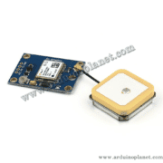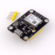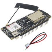
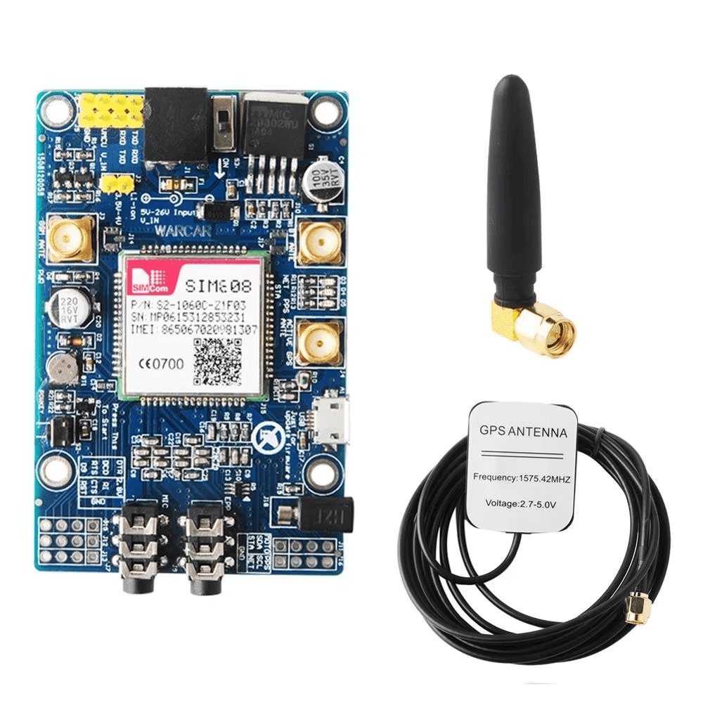
Description
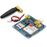
SIM808 Quad-Band GSM/GPRS + GPS Module
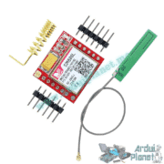
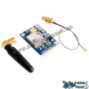
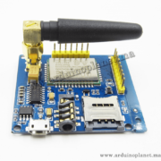
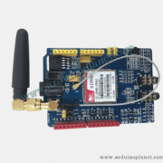
The SIM808 is an all-in-one module combining a quad-band GSM/GPRS modem and a GPS receiver (L1, 1575.42 MHz). It supports voice calls, SMS, GPRS data, and satellite positioning for telemetry, asset tracking, and mobile IoT applications. This development board includes UART connectors, a microSD slot, a battery connector, and a 1.5 m antenna to simplify integration.
Technical specifications
- Quad-band GSM/GPRS modem: 850/900/1800/1900 MHz
- GPRS: Class 12 (up to 85.6 kbps downlink and 42.8 kbps uplink)
- GPS: L1 at 1575.42 MHz, single-chip receiver (internal patch antenna plus external antenna connector)
- Supply voltage: 5 V DC via VIN or USB
- Current during calls/data: peak approximately 2 A
- Interface: 3.3 V TTL UART (TX, RX), DTR, RI, NET
- microSD slot: up to 32 GB for data or firmware storage
- Battery connector: LiPo, 3.7–4.2 V
- Antenna included: 1.5 m cable, straight SMA connector, for GPS and GSM
- Board: PCB with PWR, NET, and GPS LED indicators
- Dimensions: approximately 60 × 40 × 15 mm
Typical applications
- GPS tracking for vehicles and assets
- Weather stations or remote sensors sending data over GPRS
- Alarms and remote monitoring
- Mobile IoT interfaces
- Arduino/ESP32 prototypes with cellular connectivity and geolocation
Arduino example – sending an SMS and reading GPS
This example uses SoftwareSerial on pins 7 and 8 to communicate with the module.
#include <SoftwareSerial.h>

SoftwareSerial sim808(7, 8); // RX, TX

void setup() {
Serial.begin(9600);
sim808.begin(9600);
delay(1000);

// Vérifier communication
sim808.println("AT");
attente("OK", 1000);

// Activer GPS
sim808.println("AT+CGPSPWR=1");
attente("OK", 1000);

// Paramétrer mode GPS autonome
sim808.println("AT+CGPSRST=0");
attente("OK", 1000);

// Envoyer un SMS
sim808.println("AT+CMGF=1"); // mode texte
attente("OK", 1000);
sim808.println("AT+CMGS="+212600000000""); // numéro destinataire
attente(">", 1000);
sim808.print("Test SIM808 GPS!");
sim808.write(0x1A); // CTRL+Z
attente("OK", 5000);
}

void loop() {
// Lire position GPS
sim808.println("AT+CGPSINF=0");
if (attente("+CGPSINF:", 2000)) {
String gps = sim808.readStringUntil('n');
Serial.println("GPS: " + gps);
}
delay(5000);
}

// Fonction utilitaire
bool attente(const char* mot, unsigned long timeout) {
unsigned long t = millis();
while (millis() - t < timeout) {
if (sim808.find(mot)) return true;
}
return false;
}
Pinout and wiring
| Module pin | Description | Arduino UNO connection |
|---|---|---|
| VIN | 5 V DC supply | 5 V via USB or the 5 V pin |
| GND | Common ground | GND |
| TXD | Module TX → Arduino RX | D7 (SoftwareSerial RX) |
| RXD | Module RX ← Arduino TX | D8 (SoftwareSerial TX) |
| DTR | Reset/power control (optional) | — |
| NET | Network indicator (external LED) | — |
| GPS | GPS NMEA output (optional) | — |
| BAT+ / BAT− | 3.7 V LiPo battery (optional) | — |
- Solder the male headers, then connect VIN → 5 V and GND → GND.
- Connect TXD → 7 and RXD → 8 for SoftwareSerial.
- Connect the SMA antenna to the external antenna connector.
- Power the board over USB, then upload the sketch.
Important: The UART is 3.3 V TTL. When using a 5 V Arduino UNO, level-shift the Arduino TX signal before it reaches the module’s RXD. The supply must also handle current peaks of about 2 A.
Keywords: wireless, call, phone, location, map.