Description
GY-273 3-Axis Compass Magnetometer Module
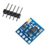
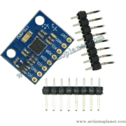
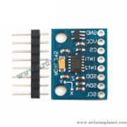
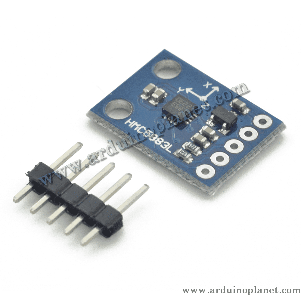
This compact board measures magnetic-field components along three axes and provides digital readings over I²C. It is listed as a GY-273/HMC5883L module. Boards sold under the GY-273 or GY-271 name may instead contain a QMC5883L or another compatible-looking sensor, so identify the actual chip before selecting a driver or relying on a particular specification.
🔧 Listed and chip-reference specifications
- Sensor: three-axis digital magnetometer; verify the exact IC marking (HMC5883L, QMC5883L or other)
- Interface: I²C; the listing states up to 400 kHz, subject to the sensor, board and host configuration
- Magnetic-field range stated in the listing: up to ±8 gauss; available ranges and resolution depend on the actual chip and configuration
- Maximum output rate stated in the listing: 160 Hz; the actual supported rate depends on the sensor variant and settings
- Board dimensions stated in the listing: approximately 18 × 17 mm
- Operating-temperature range stated in the listing: −30 °C to +85 °C; confirm against the exact sensor and assembled board specifications
- The French listing’s 2.7–6.5 V figure is not the sensor’s differential output voltage. The sensor supplies digital I²C measurements. Chip supply and I/O limits are much lower; some carrier boards add regulation or level shifting, while others do not. Check the exact board documentation and never assume it accepts 5 V.
- The listing claims 1–2° compass accuracy. This is not guaranteed for an uncalibrated board: heading accuracy depends on hard/soft-iron calibration, tilt compensation, mounting, nearby magnetic materials and the exact sensor.
🧭 Using it as a compass
Read the raw X, Y and Z magnetic-field values over I²C, then apply calibration and heading calculations in the host software. For a useful compass heading, calibrate the complete mounted device to compensate for nearby motors, magnets, steel, wiring and other sources of magnetic distortion. Tilt compensation also requires a suitable orientation reference, commonly an accelerometer. Apply local magnetic declination if converting magnetic north to geographic north.
⚙️ Wiring and compatibility
Connect the board to the host’s I²C clock and data lines, ground and the documented supply input. Confirm the board’s I²C address, chip identity, supply range and pull-up voltage. If the board does not include level shifting, keep SDA/SCL within the sensor’s logic limits and use a level shifter with a 5 V host where needed.
The listing links to both HMC5883L and QMC5883L documentation/software. These chips are not interchangeable in every detail: registers, I²C addresses, drivers and measurement behavior may differ. Check the chip marking and test the I²C response before choosing a library.
💡 Typical uses
- Magnetic-field measurement and educational experiments
- Compass-heading prototypes after calibration
- Robotics and navigation experiments when combined with suitable motion/orientation sensors
This module is for development and measurement experiments, not a certified navigation or safety instrument.