Description
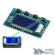
ZK-PP2K Pulse Generator and PWM Driver, 1 Hz–150 kHz
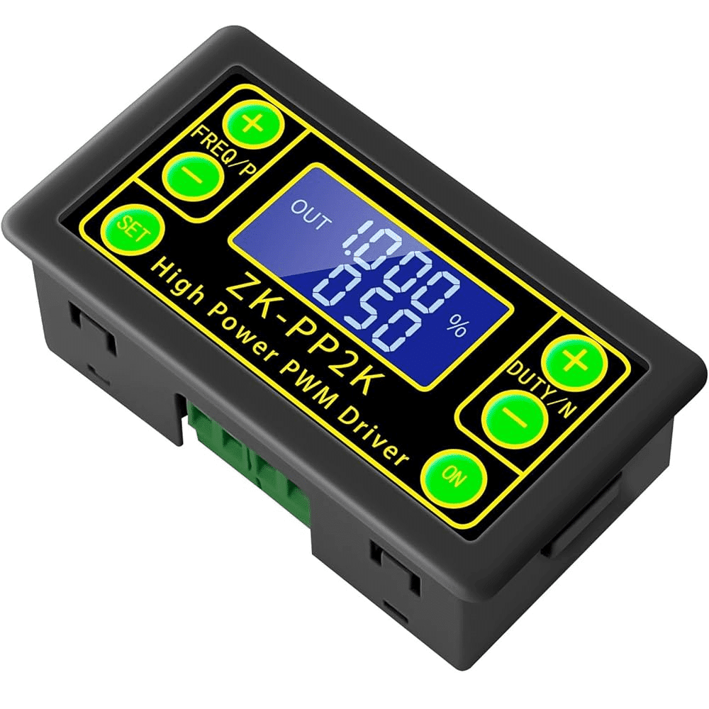
The compact ZK-PP2K generates and controls pulses or PWM signals. Its integrated MOSFET driver supports up to 8 A. It can directly drive or test LEDs, DC motors, and valves, and offers PWM and PULSE modes, a high-definition LCD, and memory for the last settings.
Technical specifications
- Model: ZK-PP2K
- Operating voltage: 3.3–30 V DC
- Frequency range: 1 Hz–150 kHz (±2%)
- Duty cycle: 0.00%–100% (0.01% steps)
- Maximum output current: 8 A (150 W maximum)
- Output modes: PWM (continuous signal) and PULSE (1–9999 pulses or continuous)
- Start delay: 0.000–9999 s (1 ms steps)
- Pulse width (PULSE): 0.000–9999 s
- Display: high-definition LCD for measurements and menus
- Functions: setting memory after power loss, output inversion, output enable/disable
- Protection: reverse-polarity protection and MOSFET thermal protection
- Operating temperature: −20 °C to +85 °C
- Dimensions: 79 × 43 × 26 mm
- User interface: 4 buttons (MODE, SET, UP, DOWN)
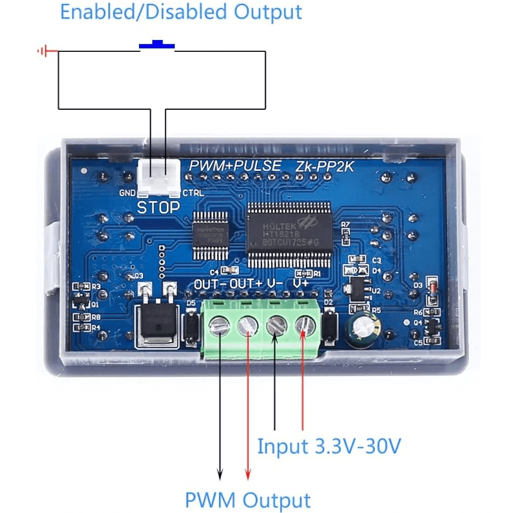
How to use and pinout
Power connection
- POWER + → 3.3–30 V DC supply (VCC)
- POWER − → ground (GND)
Load connection
- OUT + → load positive (high-power LED, DC motor, etc.)
- OUT − → load negative (common GND)
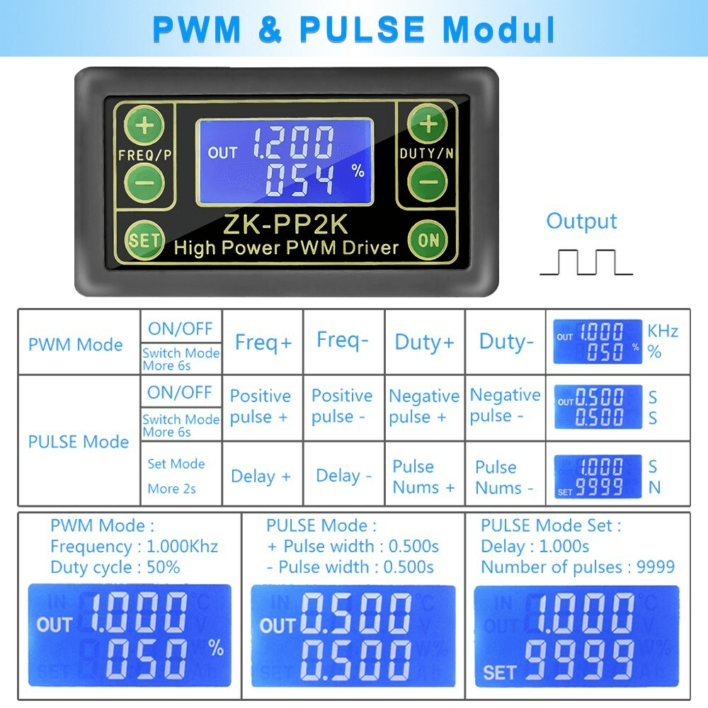
Button functions
- MODE: switches between PWM and PULSE modes
- SET: selects the parameter to adjust (frequency, duty cycle, delay, pulse count)
- UP: increases the selected value
- DOWN: decreases the selected value
Setup procedure
- Power the module.
- Press MODE to select PWM (continuous modulated signal) or PULSE (pulse count).
- When the desired parameter flashes, press SET and adjust it with UP/DOWN.
- Confirm the value by holding SET for 2 seconds.
- The output activates immediately according to the settings.
| Pin/button | Description |
|---|---|
| POWER + | 3.3–30 V DC supply (VCC) |
| POWER − | Common ground (GND) |
| OUT + | Positive output to the load |
| OUT − | Negative output (GND return) to the load |
| MODE | Selects the mode (PWM ↔ PULSE) |
| SET | Selects the parameter to adjust |
| UP | Increases the selected value |
| DOWN | Decreases the selected value |
Typical applications
- Direct control of DC motors, high-power LEDs, and solenoid valves
- Test benches for generating excitation signals
- Automation and prototyping projects (Arduino, Raspberry Pi, etc.)
- Speed adjustment and operating-cycle testing
Compatibility
- 3.3–30 V DC supply
- Suitable for test benches and prototype chassis
- Can be controlled by a microcontroller through the open-drain MOSFET output
Important notes
- Do not reverse the polarity; this may destroy the module.
- For loads above 4 A, provide a heat sink for the MOSFET.
- Observe the temperature and humidity limits.
- Keep the module away from damp or dusty environments.
Keywords: generator, pulse, oscillator.