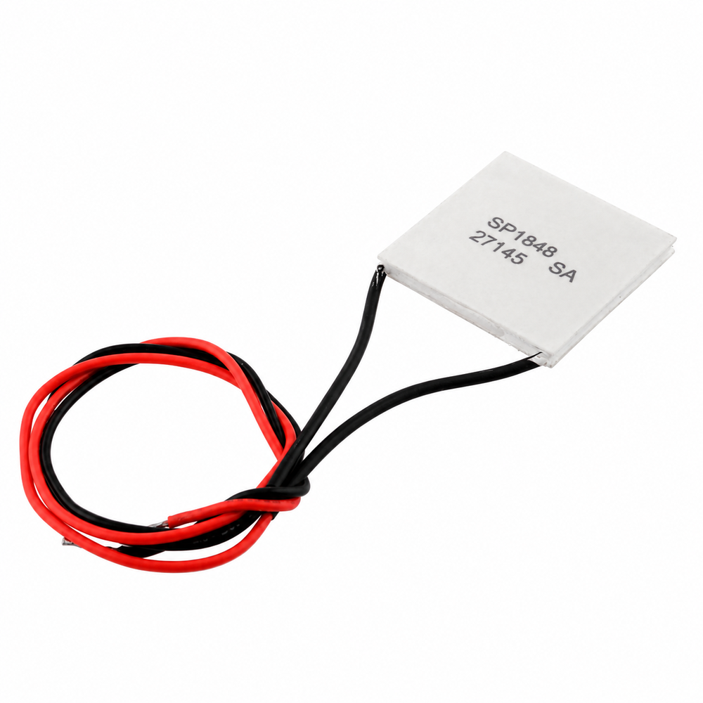
Description
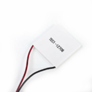
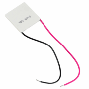
SP1848-27145 Thermoelectric Generator Module
The TEC1-SP1848-27145 generates electrical voltage from a temperature difference between its two faces via the Seebeck effect. The values below are seller-reported reference figures; real output depends on the temperature difference across the module, heat transfer, wiring and electrical load.
Specifications stated by the source
- Temperature limit stated in source: 150°C maximum (the original labels this as a voltage range)
- Open-circuit voltage: up to 4.8V, reported at a 100°C temperature difference
- Current figure reported: up to 669mA; measurement conditions are not specified
- Dimensions: 40 × 40 × 3.4mm
- Humidity protection: sealed, according to the source
- Service life claim: 200,000 hours, according to the source
- Thermoelectric couples: 127, according to the source
Reported output by temperature difference
- 20°C difference: 0.97V open circuit; 225mA reported current
- 40°C difference: 1.8V open circuit; 368mA reported current
- 60°C difference: 2.4V open circuit; 469mA reported current
- 80°C difference: 3.6V open circuit; 558mA reported current
- 100°C difference: 4.8V open circuit; 669mA reported current
The listing does not specify the load or test method for the current values. Open-circuit voltage and current under load are different operating conditions; do not treat each voltage/current pair as guaranteed simultaneous output.
Operation and wiring
Apply heat to one face and remove heat from the other to create a temperature difference. The source identifies the red wire as positive and black as negative in generator mode. Add a suitable heat sink, thermal interface material and ventilation as needed. Do not exceed the source-stated 150°C limit.
- Mount the module securely between the heat source and a heat sink; use thermal paste to improve contact.
- Connect the red wire to the input of a suitable voltage regulator or charging circuit, and black to ground.
- Monitor the temperatures of both faces and keep within the stated limit.
- Use a DC-DC converter if you need a regulated supply.
The source also mentions Peltier cooling applications, but does not provide powered-cooling ratings for this module. Check suitability before using it in that mode.
Basic Arduino Uno example
This example reads the module voltage on A0 and reports a calculated voltage over serial.
const int sensorPin = A0; // Broche où le capteur est connecté
int sensorValue = 0;


void setup() {
  Serial.begin(9600);
}


void loop() {
  sensorValue = analogRead(sensorPin);
  Serial.print("Tension générée : ");
  Serial.println(sensorValue * (5.0 / 1023.0), 2); // Conversion en volts
  delay(1000);
}
Required: Arduino Uno, this module and jumper wires.
sensorPin = A0selects the analog input.Serial.begin(9600)starts serial communication.analogRead(sensorPin)reads the analog input.
Connect the red module lead to A0 and black to GND, as shown in the source. Ensure the voltage at A0 remains within the Arduino board’s allowed input range; use suitable conditioning if needed.
Arduino example with I2C LCD
This example displays the measured voltage on a 16×2 I2C LCD.
#include <Wire.h>
#include <LiquidCrystal_I2C.h>


LiquidCrystal_I2C lcd(0x27, 16, 2);
const int sensorPin = A0;
int sensorValue = 0;


void setup() {
  lcd.begin();
  lcd.backlight();
  Serial.begin(9600);
}


void loop() {
  sensorValue = analogRead(sensorPin);
  float voltage = sensorValue * (5.0 / 1023.0); // Conversion en volts
  lcd.setCursor(0, 0);
  lcd.print("Tension: ");
  lcd.print(voltage, 2);
  lcd.print("V");
  delay(1000);
}
Required: Arduino Uno, this module, a 1602 I2C LCD and jumper wires.
- Module red lead → A0; black lead → GND
- LCD VCC → Arduino 5V; GND → GND
- LCD SCL → A5; SDA → A4
Install a compatible LiquidCrystal I2C library using the Arduino IDE Library Manager. The analog input voltage must remain within the board’s permitted range.